Renderman
Using the texmap shader with Presenter 3D
This page describes how to use Presenter 3D and
RenderMan for several different texture mapping methods: planar,
cylindrical, spherical, and wrapping.
These methods are available in a shader called
texmap, included
in the standard distribution of MacRenderMan. The maptype parameter
is used to set the mapping method. Here are some examples of the
texture mapping methods, using the tile16 texture.
|
|
Planar mapping - Projects the texture on a plane.
maptype = 0
|
|
|
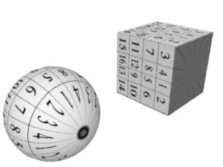
Cylindrical mapping - Projects the texture from a center axis.
maptype = 1
|
|
|
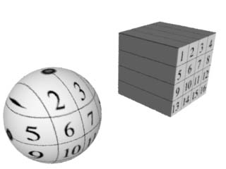
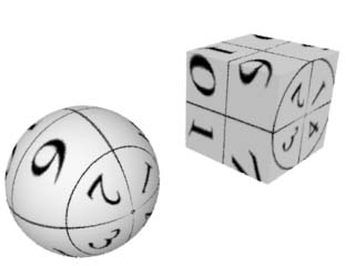
Spherical mapping - Projects the texture from a central
point.
maptype = 2
|
|
|
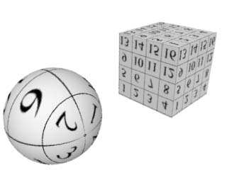
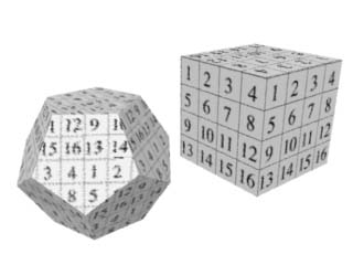
Standard mapping - Wraps the texture on the surface.
maptype = 3
|
|
|
Auto-mapping - Planar texture projection for polygons.
maptype = 4
|
The texmap shader is documented in the
MacRenderMan release notes, in a file called MRM Shader Notes Part 1. It also
uses some functions that are documented in MRM Shader Notes Part 2,
documented in the "maps" section. If you want to recompile the
shader, you must first compile the "maps.sl" functions, also included
with MacRenderMan.
The main problem with using texmap in Presenter 3D
occurs when it writes the RIB file for MacRenderMan. As it outputs
the geometric coordinates of each point, it divides the coordinates
by twelve to convert feet to inches. This conversion is unnecessary,
and complicates the process of setting shader parameters.
This problem can be minimized with a shader based
on texmap that automatically scales to the Presenter 3D coordinate
system. The new shader is called vidi_texmap.
With the new shader, you can determine the shader
coordinate parameters using the XYZ values displayed in Modeler and
Presenter, the Object Information windows, the screen rulers,
etc.
The vidi_texmap shader has an additional advantage
over Presenter's built-in texture mapping system: you can control the
Shading Rate for each object to get the best balance of quality and
rendering speed. Presenter's built-in texture mapping uses the global
shading rate for all objects.
You can download the vidi_texmap
package here. It includes the shader and
some models to demonstrate the mapping options.
vidi_texmap tutorial
As a tutorial for using vidi_texmap, let's use
VIDI Modeler to create a simple scene consisting of a sphere and a
cube.
Modeler
Some of the texture mapping methods need to
establish a center point or axis for the projection. We can use
Modeler to determine the best center point each object by setting the
Rotation Point. Double click on an object to open the Object
Information window.
Click on the pop-up menu in the Rotation Point box
and select the Center Object(s) item. This will plug the center point
into the X, Y and Z fields. We will refer to these values in the
Presenter application.
Presenter
Switch from Modeler to Presenter and open the
model.
Double-click on one of the object to open the
Object Info window. Note that the Rotation Point set in Modeler is
now displayed in the Center X, Y and Z fields (X=-1.5, Y=0.5,
Z=0.5).
Next, open the Attributes window and switch the
view to "Shaders" in the popup menu. Find the vidi_texmap shader in
the list and drag it to the bin in the Object Info window.
Double-click on the vidi_texmap icon in the Object
Info window to open the Shader Parameters window. There are four
parameters that must be set to establish the center point for texture
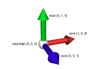
mapping:
- maporigin
- xaxis
- yaxis
- zaxis
Each parameter is a three-dimensional point. It's
easiest to start by entering the same X, Y and Z values into each
parameter. The point can be positioning the arrow cursor over the
desired point and getting the current coordinates from the X, Y, Z
feedback in the upper-right corner. But it is faster and more precise
to simply use the Rotation Point values we set earlier in
Modeler.
Find the Offset X, Y, Z values in the Object
Window, and enter them into the maporigin, xaxis, yaxis and zaxis
parameters.
Next, you must modify the axis values to establish
the direction of the projection. To start out, it is easiest to
simply add 1 to the appropriate field of each axis:
- Increment the xaxis X value + 1.
- Increment the yaxis Y value + 1.
- Increment the zaxis Z value + 1.
This will align the longitude of the texture along
the Z axis. If the camera is positioned in front of the model, you
will probably be looking at the top of the texture on the object.
This orientation can be changed by swapping the point coordinates of
two axes.
The "maptype" value must also be set to indicate
the texture mapping method to be used:
- maptype = 0 for
planar mapping
- maptype = 1 for
cylindrical mapping
- maptype = 2 for
spherical mapping
- maptype = 3 for
standard mapping
- maptype = 4 for
auto-mapping
The other parameters include the usual plastic
shader parameters (Ka, Ks, Kd, roughness and specularcolor).
Of course, there is a parameter for the texture
file name. Since the vidi_texmap shader bypasses Presenter's
automatic texture mapping functions, you must convert a PICT file to
the ".tex" format before rendering. This can be done by using
Presenter's built-in texture mapping system for one shot, then using
the .tex file left after rendering. Or you can write a short RIB that
contains the appropriate MakeTexture statements, and submit it to
RenderApp to create the .tex file.
The s and t parameters (s1, t1, s2, t2, s3, t3,
s4, t4) control the scale and orientation of the texture, and can be
used for tiling purposes. In some cases, they can flip the texture
vertically and horizontally. See the MacRenderMan release notes about
texmap for details on usage of these parameters, which vary depending
on the mapping method.
In addition to the standard texmap shader
parameters, vidi_texmap includes three more parameters: scale_xyz,
scale_s and scale_t. These are used to translate the shader
coordinates back to the Presenter coordinate system. The default
value for the scale parameters is 12, but it is appropriate to set
other values depending on the mapping method. The example models
included with the shader show some of the different scale
settings.
Copyright © 1997 by
WebNation
All trademarks are the property of their respective holders
Switch to
Standard View