
Presenter 3D provides powerful and intuitive Behavioral Kinematics(tm) controls for creating character animation, facial expressions, and lip syncing. The new Morph Hint feature provides you with the ability to combine a variety of morph instancing targets (utilizing both reshape and rotate operations) into a single control slider. This instancing capability for creating a variety of expressions enables you to define a complex facial expression or body movement that can be applied at any frame of an animation. This new morphing technology allows Presenter 3D to offer the same IK (Inverse Kinematics) and Bones effects provided by workstation products, but at a more productive, intuitive, faster processing, less memory intensive, and less expensive level.
The order in which you construct a model for character and lip sync animation with Presenter 3D is:
1) Create the Model
Model the component parts of your character using Presenter 3D's Modeler module with the minimum number of separate parts within a hierarchical group structure. While it would be optimal to create the human body as one piece, it's more likely that you will create the head, body, arms, legs, and fingers as separate parts as shown in Fig. 1. You may also want to create the eyes, eyebrows, and lips as separate parts.
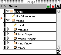
Fig. 1 - Group Window |
Fig. 2 - Group Menu |
2) Define the Instancing Target Shapes and Rotations
Select the parts that will change shape or will be rotated by clicking on the name of the object in the group window The "Upr&LwrArm will be the first part to be changed. Select the Morph option in the Group Menu as shown in Fig. 2 above. This brings up the Morphing Object dialog box for the selected part as shown in Fig. 3 below. Click on the Add button to create a new target. To change the name of a target, click at any point of the name and backspace to remove letters and type to add the new name. To bend the arm, click on a point near the middle of the arm as shown by the arrow in Fig 4 and click on the Rotation Point popup as shown by the arrow in Fig. 3.
Fig. 3 - Morph Dialog |
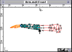
Fig. 4 - Select Bend Points |
Drag to the Selected Vertex(s) option as shown in Fig. 5 below.
Using the Selector tool (the arrow or typing the letter S), drag a rectangle around the points comprising the forearm to select them as shown in Fig. 4 above.
Select the Rotate tool (type R), click in the same place as defined by the arrow in Fig. 4, click and hold on the left part of the arm and drag down to create the bend as shown in Fig. 6. Don't worry about the hand not moving with the arm, this will be connected later.
Click on the point at the bend of the arm and click and drag the control point indicated by the left-most arrow to correct the curve at the elbow. The points indicated by the two arrows at the right of Fig. 6 are dragged down to create the muscle bulge as the arm is bent.
Fig. 5 - Select Rotation Point |
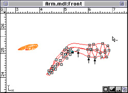
Fig. 6 - Bend Arm |
Notice in Fig. 7, that the object symbol (the straight pencil) has changed to the morph object symbol (a bent pencil). You can add additional morph targets to the same object. To add a rotation morph target, click on the Add button in the Morphing Object dialog. This time, select a rotation point at the top of the arm and select all the points. Select the Rotate tool and rotate the entire arm.
Using the same technique, you can add morph targets to the remaining parts of the arm to create the desired changes to shapes and rotations.

Fig. 7 - Group Window |
Fig. 8 - Group Menu Showing Hints |
3) Use the Instancing Targets to Create the Instancing Expressions
Now that you have a folder with morph objects inside you can add a morph hint to the folder to combine the morphs into instances (expressions) controlled by a single slider.
Select the folder and select the Morph Hints option in the Group Menu as shown in Fig. 8 above. This automatically creates a Morph Hints object as shown in Fig. 9 below.
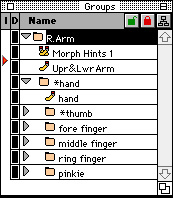
Fig. 9 - Group Window |
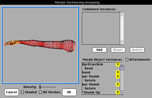
Fig. 10 - Instance Window |
Once you have made a morph hint group, you can access the hint information by double-clicking on the hint group in the group list. You will then be presented with the dialog as shown in Fig. 10 (without any combined instances set yet). This dialog has a large preview rendering area with an option for showing the model in wireframe or shaded form.
The preview window is hot and can be rotated left/right and up/down by clicking and dragging within the window. Controls beneath the preview window allow for changing the smoothness and display type of the model. The Density of the mesh can be changed to a finer break-up by dragging the slider or clicking anywhere on the Density line. The Shaded check box allows either a spline mesh or a shaded mesh to be viewed. The All Meshes check box will allow the viewing of other standard spline meshes within the hint folder. This allows you to see how the morph mesh interacts with any standard mesh.
The Morph Object Instances area is found at the bottom, right of the Instances Grouping window. All the morph groups appear with a yellow letter on the right. Under each group, the morph instances for that group will be listed. The yellow letter at the right is the rotation axis for the object group. You can change the axis of rotation by clicking on it.
For this example, the forearm group was turned off in the group list. This allows the morph dialog to center and display the hand/fingers as the main area of interest and improves redraw time by removing unneeded elements for display. All Morph objects are displayed, even if turned off in the group list.
Attaching Separate Parts
In addition to providing smooth shaping and morphing of objects, Presenter 3D provides the ability to connect objects similar but more effective and efficient than Inverse Kinematic chains. If the Attachments checkbox is used, the Morph Object Instances will show just the group names and the instances will disappear. The sliders at the right (that appear once combined instances are created) are replaced with a list of which group the selected group is attached to. Each group can only be attached to one other group.
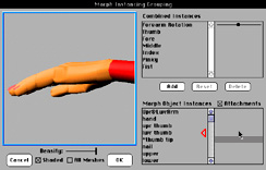
Fig. 11 - Select Object To Attach |
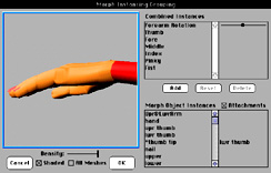
Fig. 12 - Select Object To Be Attached To |
To attach the thumb tip to the lwr thumb object, click and hold in the Attachments box next to the thumb tip object. Drag up the lwr thumb object. You will see a red arrow track along the names area as shown in Fig. 11 above. Release next to the object name, lwr thumb, causing this name to appear next to the thumb tip name as shown in Fig. 12 above indicating that these two parts are connected. The way attachment works is to find a vertex on the object you have attached to. Then all the movement applied to that vertex when any morph is applied to the lwr thumb object will also be applied to the attached object.
Continue this process until you have attached all the finger parts, the hand, and the arm. Now you will be able to bend all the separate parts and be confident that they will move together properly. Click in the Attachments box to turn off the Attachments mode. This will make all the instances re-appear.
Creating Behavioral Expressions With Combined Instances
Creating behavioral expressions from instances involves adding a Combined Instances element and selecting the Morph Object Instances making up the combined instance. We'll examine the use of sliders in defining different lip expressions starting with Fig. 13.
The slider to the right shows the amount of the combined instance being used. When you wish to work on a single combined instance, double-click on the name and all the other combined instances will be set to zero and the combined instance of interest will be set to one. The Add button will create a new combined instance. The Reset button will return the combined instance to a zero object reference. What this means is that all the object instances settings for the combined instance will return to zero and you can start again. The Delete button will remove the current active combined instance.
The sliders for the instances control the amount of the instance applied. This can vary from -2 to +2. The values 1, 0, and -1 are 'sticky'. You can either drag the slider or click on the point in the range that you want to move the slider to. The color of the slider also changes to show the general zone you are in.
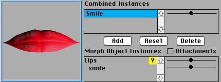
Fig. 13 - Closed Lips |
The starting position is shown in Fig. 13 with all the instances at the zero position. From this position, you can create a smile or a frown with just the drag of the slider. The range 0 to 1 represents a change in the instance between 0% to 100% and is colored green as shown in Fig. 14. Zero represents the original position of the object with no morph instance applied and 1 represent the full application of the instance.
Drag the black slider for the Smile Combined Instance to the right. As long as you are in the green range, the value is between 0 and 1. To create the desired expression, drag to the right to make the mouth open into a full smile as shown in Fig. 14.
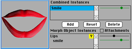
Fig. 14 - Full Smile |
The range 0 to -1 represents a change in the instance between 0% to -100% and is colored red as shown in Fig. 15. Zero represents the original position of the object with no morph instance applied and -1 represent the full application of the instance in reverse in this case down instead of up.
Drag the black slider for the Smile Combined Instance to the right. As long as you are in the red range, the value is between 0 and -1. To create the desired expression, drag to the left to make the mouth open into a frown as shown in Fig. 15.
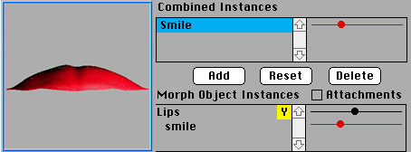
Fig. 15 - Full Frown |
The range 1 to 2 represents a change in the instance between 100% to 200% and is colored yellow as shown in Fig. 16. One represents the full application of the instance applied and 2 represents doubling the effect of the application of the instance.
Drag the black slider for the Smile Combined Instance to the far right. As long as you are in the yellow range, the value is between 0 and 1. To create the desired expression, drag to the right to make the mouth open into an exaggerated smile as shown in Fig. 16.
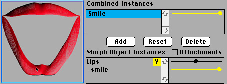
Fig. 16 - Exaggerated Smile |
The range -1 to -2 represents a change in the instance between -100% to -200% and is colored purple as shown in Fig. 17. Minus one represents the full application of the instance in reverse and minus 2 represents doubling the effect of the application of the instance in reverse.
Drag the black slider for the Smile Combined Instance to the far right. As long as you are in the purple range, the value is between -1 and -2. To create the desired expression, drag to the right to make the mouth open into an exaggerated frown as shown in Fig. 17.
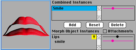
Fig. 17 - Exaggerated Frown |
These examples represent the simplest of the expressions that can be created with Presenter 3D. In the following section, it will become clear that full character, facial, and lip sync animations are intuitive and effective to produce.
Combining Instances To Creat a Finger
With an understanding of the operation of instances and with all the necessary arm parts attached, you can proceed to create combination instances. For this example, you will cause the pinkie finger to bend down and curl.
To start, click on Add. The name Combo01 appears in the Combined Instances area at the top, right of the Instances window. A slider appears to the right of the name and sliders appear for all the elements in the Morph Object Instances area. The slider next to the group name is for the rotation of the group.
The first combined instance will be for the pinkie finger. Start by changing the name of the combination to Pinky by clicking to the right of the name Combo01 and hitting the delete key and then typing the new name as shown in Fig. 18 below.
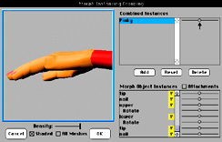
Fig. 18 - Fingers Extended |
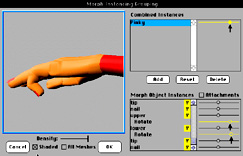
Fig. 19 - Finger Bent |
To start the combined instance, drag the slider next to Pinky to the right as shown in Fig. 19 above. To set the bend of the finger, first drag the slider next to the upper rotate instance to the right.
Next, drag the slider next to the lower rotate instance to the right. This sets the bend of the pinkie finger which is controlled by the Pinky slider in the Combined Instances area.
Each finger can be bent and assigned a combined instance slider. By applying all the finger instances to a single slider, you can open and close the hand with a single slider as shown in Fig. 20 below.
By turning the remaining parts of the arm on and assigning the arm bend instance to the Forearm-Rotation combined instance and moving this slider and the Fist slider to the right, you can bend and flex the arm as you close the hand into a fist as shown in Fig. 21.
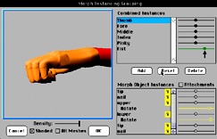
Fig. 20 - All Fingers Bent |
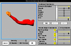
Fig. 21 - Arm Bent |
With the ability to combine instances to produce complex behavioral expressions, you now are ready to animate the rest of the body to make characters walk, run, and talk. Check out the Face Sculpt example to see how to model a face and the Lip Sync example to see how to sync facial expressions to dialogue.